DVL-5000
DVL-5000 is a DVXplorer based Laser Scanning product.
General Overview
The components of the DVL-5000 can be divided into three parts:
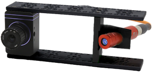
The sensor itself, consisting of the DVXplorer, the laser, and the laser mounting parts
A host computer, which interfaces the Raspberry Pi using the DV-GUI
The Raspberry Pi, on which the DVL-5000 software runs
Getting Started
Preparing the Sensor
The sensor can be assembled very easily using the assembly instructions delivered with the DVL-5000 components.
Preparing the Host Computer
In order to prepare the host computer, please refer to the general installation guide. In order to use the DVL-5000, only the DV-GUI is needed, however, in order to develop your own modules based on the DVL-5000, or for DV algorithms in general, it is suggested to install the DV-SDK as well.
Connecting to the Raspberry Pi
Setting up a TCP Connection Between the Raspberry Pi and the Host Computer
The Raspberry Pi comes preinstalled with all necessary components. Whenever the Raspberry Pi is booted, the DVL-5000 software is automatically started as a Linux service. To connect to the Raspberry Pi, please refer to the official documentation. In order to use the DVL-5000, you will need to connect to the Raspberry Pi either via WiFi or Ethernet.
If a DNS is available, the Raspberry Pi can be reached via the hostname dvl-5000.
Connecting DV to the Raspberry Pi
Once the Raspberry Pi is powered up and reachable, a connection to DV can be established as follows:
Open DV
Select
Connect to→Connect to remote runtimeEnter the IP address or hostname of the Raspberry Pi
For the port number, enter 4040
Obtaining the Sample Configurations
The sample configurations for the DVL-5000 are available
here as a .tar.gz archive and
here as a .zip archive. They should be stored on the host
computer, and can be opened in DV by selecting File → Open project.
Obtaining Software Updates
Software updates can be obtained by logging in to the Raspberry Pi, and running the bash script available from
this link. The username on the Raspberry Pi is ubuntu, and
the password is dvl-5000.
ssh ubuntu@dvl-5000.local
wget https://release.inivation.com/dvl-5000/dvl-5000-setup.sh
sudo bash ./dvl-5000-setup.sh
If there is no DNS available, instead of dvl-5000, you need to specify the IP address.
The available options are as follows:
Usage:
    dvl-5000-setup.sh -h | --help                    Display this help message.
    dvl-5000-setup.sh                                Install the latest version of all components.
    dvl-5000-setup.sh -<component>=<version>         Install a specific version of a certain component.

Components:
    -p, --dv-laser-profiler                          dv-laser-profiler
    -c, --dv-laser-profiler-calibration              dv-laser-profiler-calibration
    -r, --dv-point-cloud-renderer                    dv-point-cloud-renderer
    -h, --dv-point-cloud-running-heat-map            dv-point-cloud-running-heat-map
    -o, --dv-point-cloud-csv-output                  dv-point-cloud-csv-output
    -l, --dv-latency-measurement                     dv-latency-measurement

Versions:
    MAJOR.MINOR.PATCH                                specific version
    latest                                           latest release
    master                                           latest master branch (unstable track)
Calibration
Camera Calibration
For the calibration of the profiler to be conducted, the camera itself needs to be calibrated.
Preparation:
Open DV.
Select
Connect to→Remote runtimeand enter the IP address of the DVL-5000. The port is4040.If the DVL-5000 is connected to a DNS, you can enter
dvl-5000instead of the IP address.
Open the DV configurations downloaded from the release site: .tar.gz or .zip.
Select
File→Open projectand select the path to the folder to which you extracted the downloaded archive containing the DV configurations.Select the DV configuration named
dvl-5000-camera-calibration.xml.
Plug in the DVL-5000.
Mount the DVL-5000 to the place of its intended use.
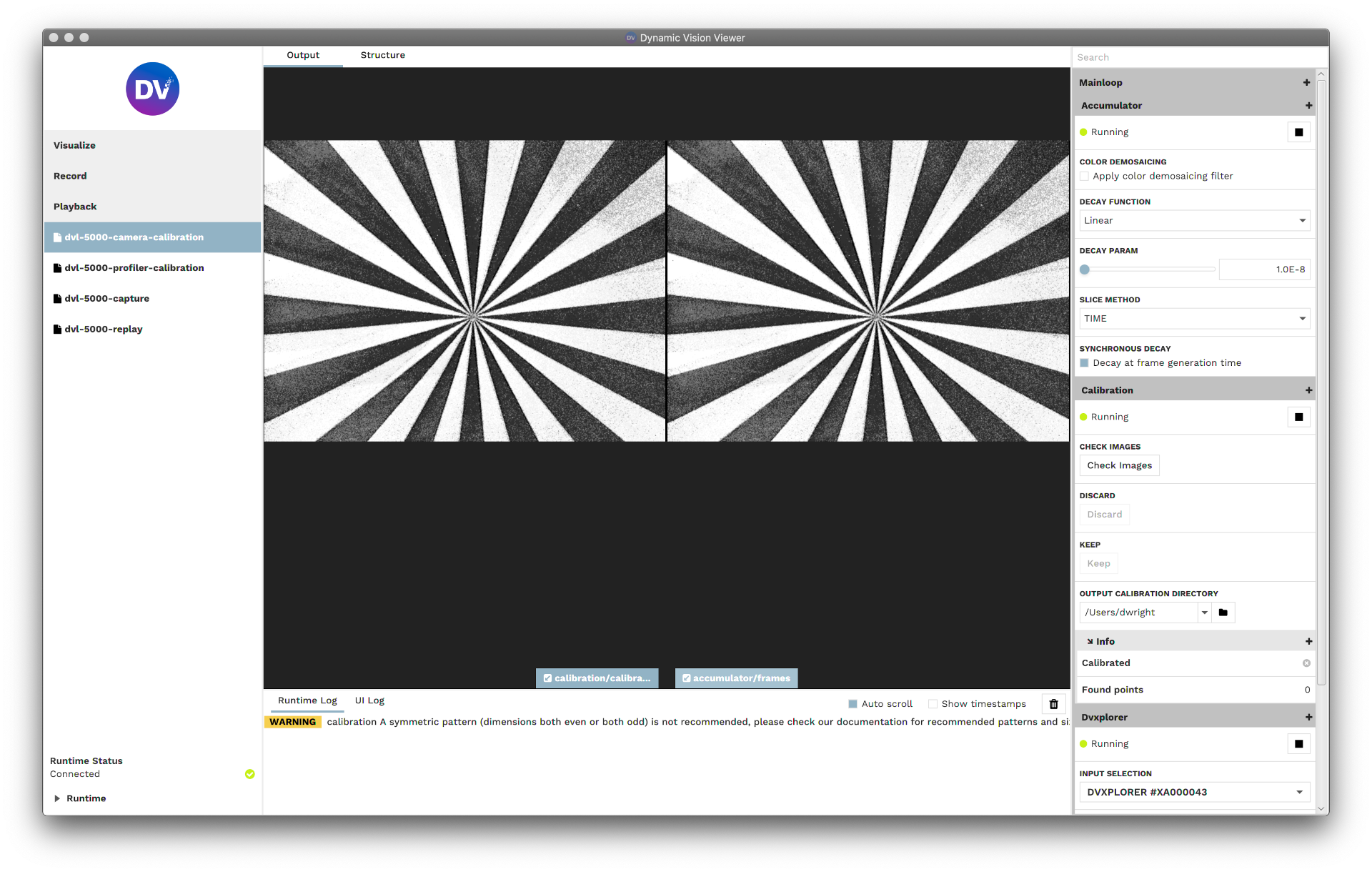
Print out the Siemens Star and the camera calibration pattern.
Start all of the modules, and switch to the
Outputtab in DV.Focus the lens using the printed Siemens Star.
Open up the aperture completely using the lens’ ring that says
openandclose.Adjust the field of view to cover the desired measurement range using the lens’ ring that says
nearandfar.Focus of view using the lens’ ring that says
teleandwide. When the lens is perfectly in focus, the centre of the Siemens Star is visible without any shade.
Lock all of the rings on the lens using the screws in them.
Execution:
Move around the camera calibration pattern in front of the DVL-5000.
Once the calibration pattern is detected, the area in which it was detected will gradually be covered in a green overlay. Try to cover as much of the frame in green as possible.
Once enough calibration points have been collected, they will be displayed again for review. They can be accepted or rejected by clicking
keepordiscard, respectively.After the collected images have been reviewed, the calibration is calculated, and the results are displayed in the runtime log.
If the reprojection error is in an acceptable range, the calibration results are stored in
/home/ubuntu/calibration_camera.xml.
For more in-depth information on the camera calibration, please refer to the camera calibration tutorial.
Profiler Calibration
After the camera is calibrated, the profiler can be calibrated.
As described above, the DVL-5000 should already be mounted to the place of its intended use.
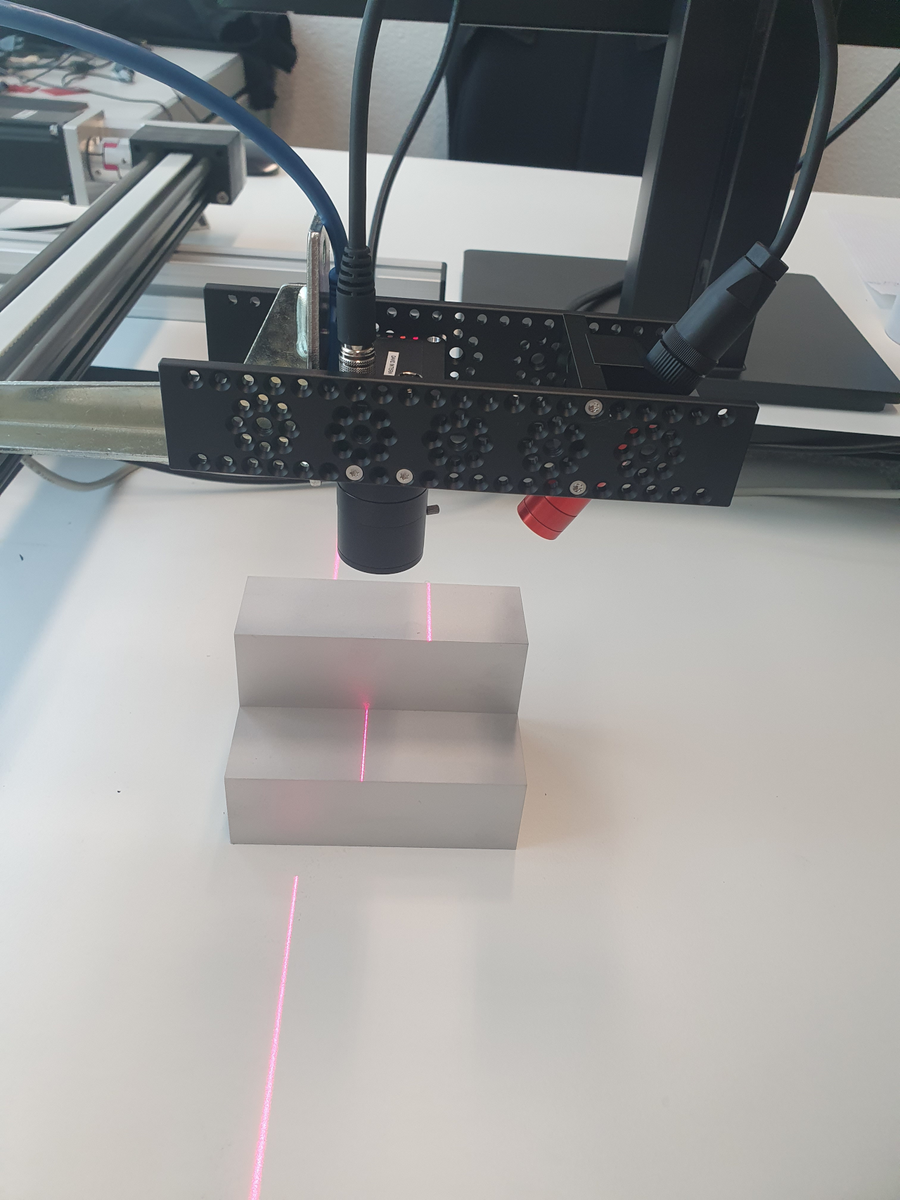
Place the calibration object in front of the DVL-5000.
The laser line should be visible on all levels of the calibration piece.
The pictures below show how the DVL-5000 and the calibration object should be positioned.
Make sure the laser is focused for its intended measurement range.
Open DV.
Select
Connect to→Remote runtimeand enter the IP address of the DVL-5000. The port is4040.If the DVL-5000 is connected to a DNS, you can enter
dvl-5000instead of the IP address.
Open the DV configurations downloaded from the release site: .tar.gz or .zip.
Select
File→Open projectand select the path to the folder to which you extracted the downloaded archive containing the DV configurations.Select the DV configuration named
dvl-5000-profiler-calibration.xml.
Start all of the modules, and switch to the
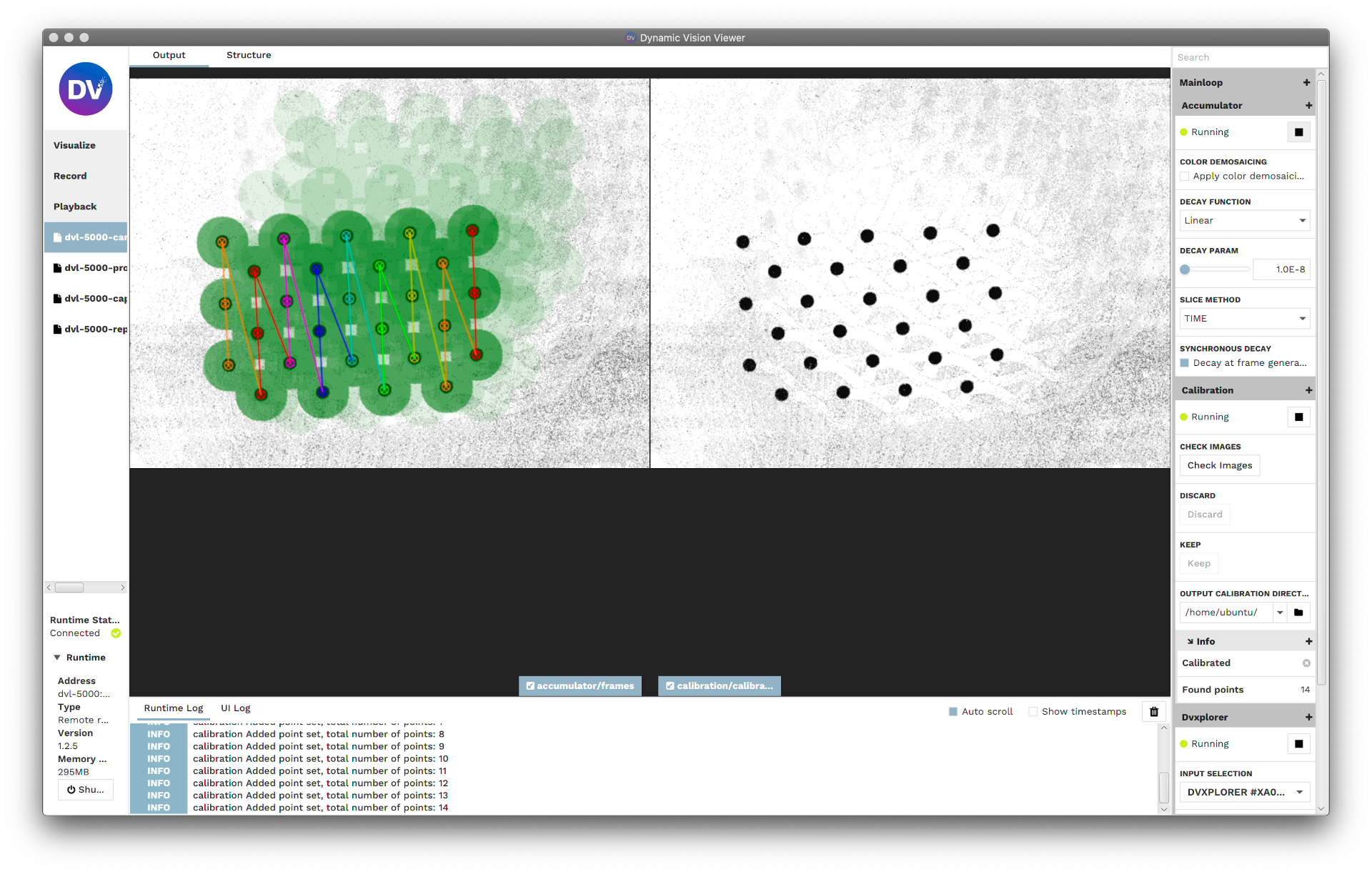
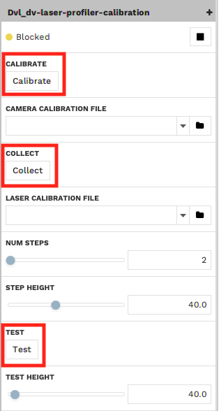
Outputtab in DV.Click “Collect” in order to collect calibration data.
The “Collect” button is highlighted in the figure below.
Click “Calibrate” in order to conduct the calibration.
The “Calibrate” button is highlighted in the figure below.
The figures below show an example physical setup for the calibration and the resulting output in DV.
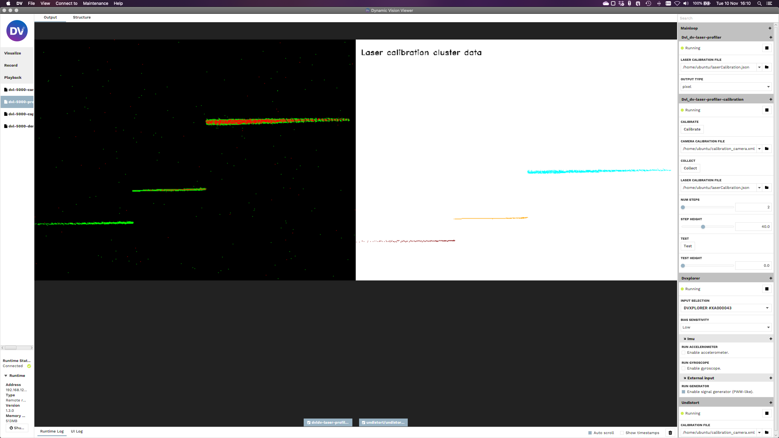
The figure below shows the highlighted buttons for the calibration and testing.
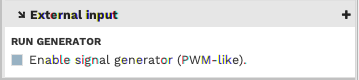
The DVL-5000 should be running automatically. If it is not running, enable the DVL-5000 by checking the box “Enable signal generator” under the external input configuration.
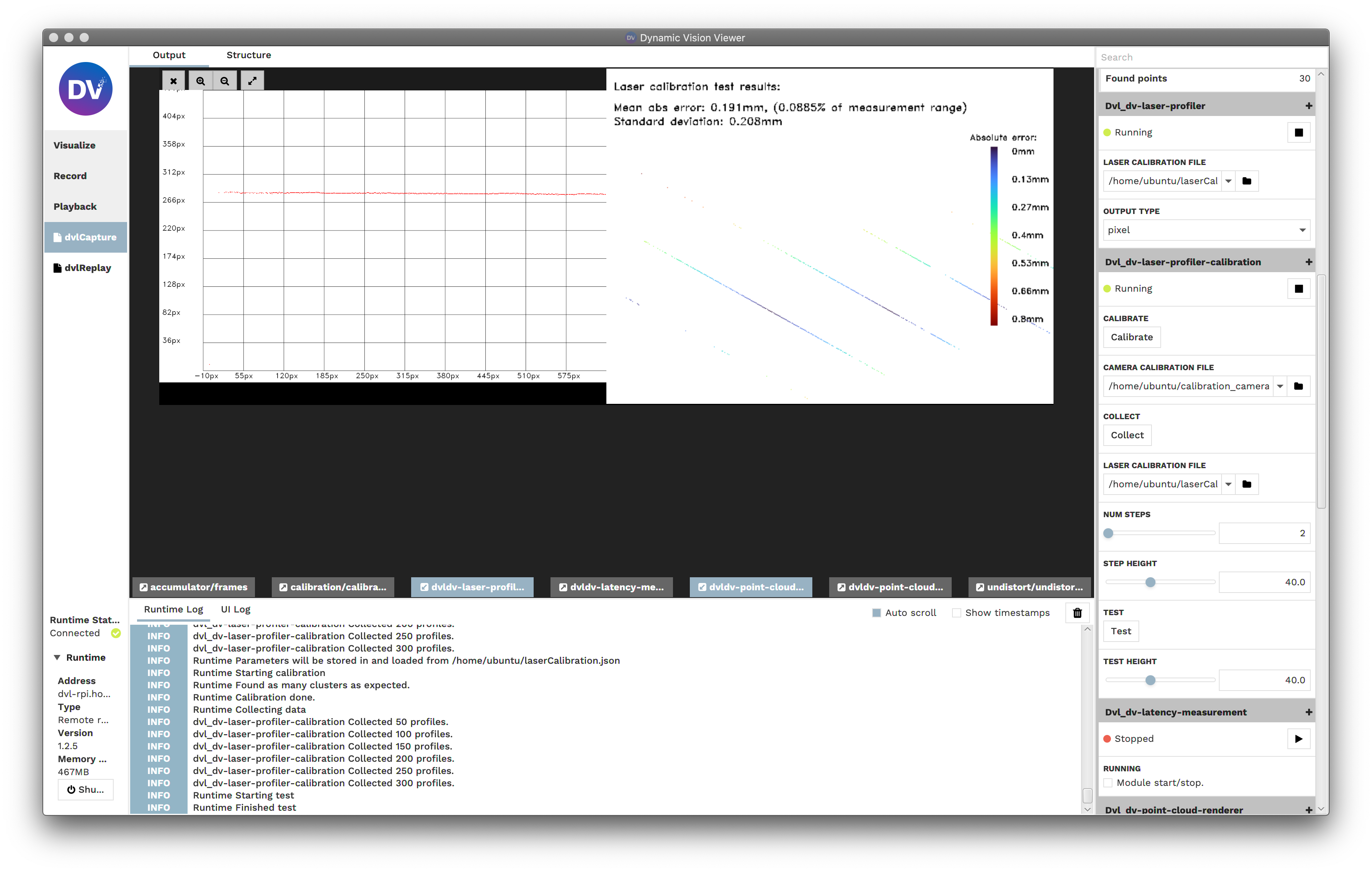
Testing the Calibration Results
The calibration results can be tested with an object of constant height that covers the whole DV sensor. It is also possible to test with the DVL-5000 pointed on the ground plane (i.e. the test height being 0).
The test is conducted as follows:
Point the DVL-5000 at the ground plane.
Open DV.
Select
Connect to→Remote runtimeand enter the IP address of the DVL-5000. The port is4040.If the DVL-5000 is connected to a DNS, you can enter
dvl-5000instead of the IP address.
Open the DV configurations downloaded from the release site: .tar.gz or .zip.
Select
File→Open projectand select the path to the folder to which you extracted the downloaded archive containing the DV configurations.Select the DV configuration named
dvl-5000-profiler-calibration.xml.
Start all of the modules, and switch to the
Outputtab in DV.Click “Collect” in order to collect calibration data.
The “Collect” button is highlighted in the figure below.
Click “Test” in order to conduct the test.
The “Test” button is highlighted in the figure below.
The figure below shows the highlighted buttons for the calibration and testing.
Once the test is finished, a visualization of the error distribution of will be displayed, as shown below. The collected data are colour coded based on their measurement error, with a colourbar displayed on the right.
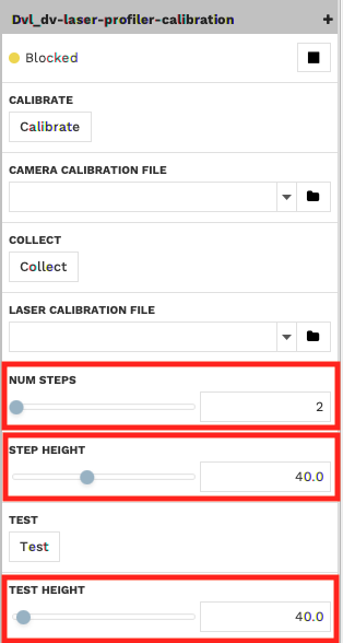
Advanced Calibration targeted at Specific Object Sizes and Measurement Ranges
While the calibration piece provided is targeted at a very wide measurement range, it may be useful to calibrate for a
smaller or larger range. The dv-profiler-calibration module allows for any calibration object to be used, provided
there are more than three different levels of height, the difference in these levels being constant. For example you use
a stair with five steps, as long as the step heights is the same for all steps.
The advanced configuration options for the profiler calibration module are shown in the image below. In order to use a
custom calibration object suited specifically for your application, you can modify the step height (in mm) and the
number of steps.
Scanning
Module Structure
A sample configuration for running, visualizing, recording, and exporting scans with the DVL-5000 is available on the iniVation release server. A screenshot of the structure is shown below.
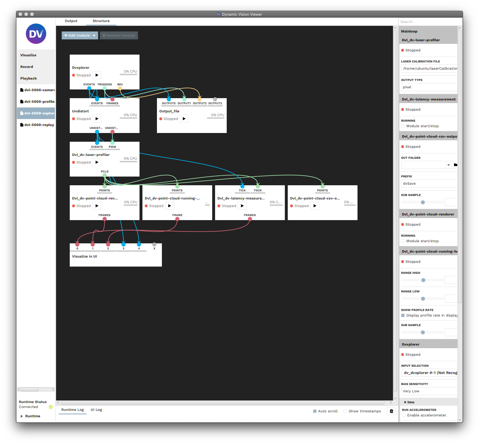
Module Descriptions
Module |
Description |
|---|---|
DV Undistort |
Undistortion of captured events. |
DVL Laser Profiler |
Extraction of laser line from events and mapping of extracted laser line into 3D space. |
DVL Point Cloud Renderer |
Rendering of extracted profiles on a 2D graph. |
DVL Running Heat Map |
Rendering of extracted profiles in a running heat map. |
DVL Latency Measurement |
Measuring latency between captured events and computed point cloud. |
DVL Point Cloud CSV Output |
CSV export of point cloud data. |
Module Configuration
Module |
Configuration |
|---|---|
DV Undistort |
Set the camera calibration path. |
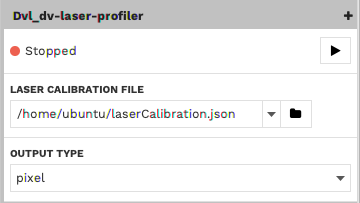
DVL Laser Profiler |
The output unit can be chosen between |
DVL Point Cloud Renderer |
No configuration necessary. |
DVL Running Heat Map |
Select the data range which should be displayed (in the same units as selected for the profiler). A subsampling rate may be chosen if needed. |
DVL Latency Measurement |
No configuration necessary. |
DVL Point Cloud CSV Output |
Set the path to the output file. |
Running the DVL-5000
Open DV.
Select
Connect to→Remote runtimeand enter the IP address of the DVL-5000. The port is4040.If the DVL-5000 is connected to a DNS, you can enter
dvl-5000instead of the IP address.
Open the DV configurations downloaded from the release site: .tar.gz or .zip.
Select
File→Open projectand select the path to the folder to which you extracted the downloaded archive containing the DV configurations.Select the DV configuration named
dvl-5000-camera-capture.xml.
In the profiler’s calibration options, select between
pixelandphysicalfor the output type.Start the desired modules, and switch to the
Outputtab in DV.
The DVL-5000 should be running now. If it is not running, enable the DVL-5000 by checking the box “Enable signal generator” under the external input configuration.
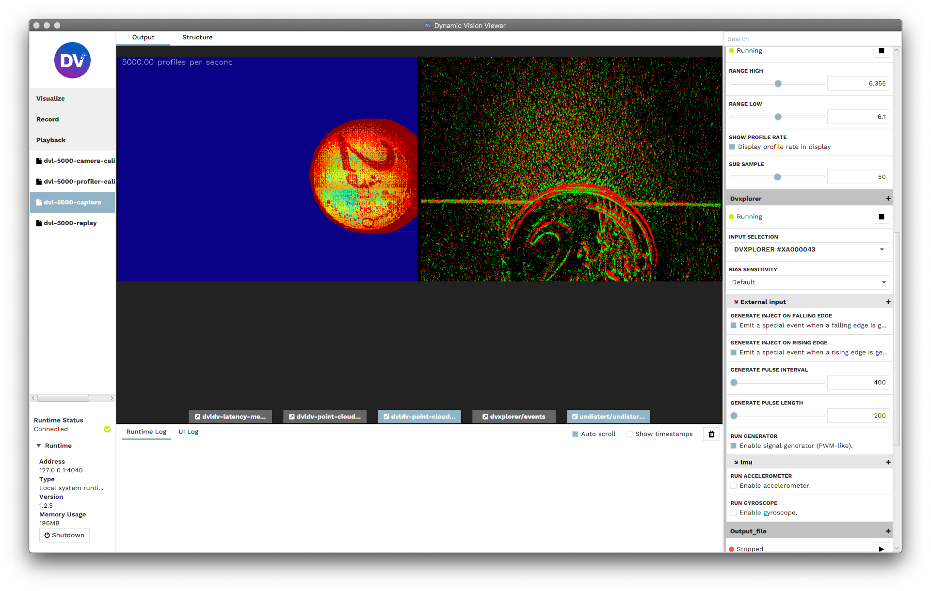
The figure below shows a sample output of the DVL Running Heat Map module.
Notes for Obtaining the Best Possible Results
Always undistort the events using the dv-undistort module.
Focus the lens using a Siemens Star.
Try to get a good depth of focus by reducing the aperture, but make sure that the laser line is still visible.
Focus the laser to the region of interest.
The bias settings in the DVXplorer module have an impact on the quality of the extracted laser line.
If the object to be scanned is very close to the DVL-5000, lower bias settings tend to yield better results.
If the object to be scanned is farther away from the DVL-5000, higher bias settings tend to yield better results.
If possible, ensure that the measurement range covers the entire image range.
Safety Information
To prevent damage to property or injury to yourself or to others, read this safety information in its entirety before using this product.
This product is intended to be used in a laboratory and for industrial applications under controlled conditions.
We strongly recommend that you only use high quality USB cables, like the ones provided by iniVation. Using low quality USB cables could cause damages to the device.
Keep the product dry. Do not handle the product with wet hands. Do not handle the plug with wet hands. Do not operate the camera near water. This could cause damage to the device. The camera is not water-safe.
Handling: Handle your product with care. It is made of metal, glass, and plastic and has sensitive electronic components inside. The product can be damaged if dropped, burned, punctured, or crushed, or if it comes in contact with liquid. If you suspect damage to the product, please contact iniVation.
Repairing: Do not open the product and do not attempt to repair the product yourself. Disassembling the product may damage it and will void your warranty. If your product is damaged or malfunctions, please contact iniVation.
Do not disassemble or modify this product.
Do not touch internal parts that become exposed as the result of a fall or other accident.
Keep this product out of reach of children. Should a child swallow any part of this product, seek immediate medical attention.
Use travel converters or adapters designed to convert from one voltage to another or with DC-to-AC inverters.
Explosive and other atmospheric conditions. Connecting or using the product in any area with a potentially explosive atmosphere, such as areas where the air contains high levels of flammable chemicals, vapors, or particles (such as grain, dust, or metal powders), may be hazardous. Exposing the product to environments which have high concentrations of industrial chemicals, including near evaporating liquified gasses such as helium, may damage or impair the product’s functionality.
Turn this product off when its use is prohibited.
Do not leave the product where it will be exposed to elevated temperatures for an extended period such as in an enclosed automobile or in direct sunlight. This can lead to malfunction.
Correct Disposal

This product and its electronic accessories should not be disposed of with
other household waste. If you are unable to dispose of this item safely please return it to iniVation AG.