Frequently Asked Questions
General Questions
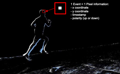
What is a DVS?
DVS (Dynamic Vision Sensor) is a type of sensor that transmits only pixel-level changes. Unlike traditional image
sensors that capture full frames at a fixed rate, DVS sensors are much faster and more efficient. Additionally, they
have a very high dynamic range and a very low latency.
Davide Scaramuzza, Robotics and Perception
Group, University of Zurich
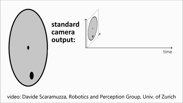
Below is a comparison between a more realistic frame and the corresponding event output with an explanation of what an event is.
Realistic Image from Frame Camera |
Corresponding Output from Event Camera |
|---|---|
|
|

Read more about events and temporal resolution in our White Paper.
How do I use my Event Camera?
iniVation cameras are usable with our different software solutions.
I think I need both events and frames in my applications. Which camera should I choose?
All iniVation cameras provide pixel-level event output. In addition, all iniVation cameras support software reconstructed frames of intensity images, using the event output processed by iniVation’s DV Software. DV Software contains several algorithms to reconstruct frames of intensity images from events. Each of these algorithms has different characteristics affecting image quality and processor requirements.
In addition, the DAVIS346 camera can directly output conventional frames of hardware-measured intensity images. These are the same as the frames from conventional image sensors. The conventional frame output from the DAVIS346 is limited to 55 dB dynamic range and 40 FPS frame rate. Please refer to the DAVIS346 specifications for further details.
Software reconstructed frames (from events) work best for specific use cases where image quality is not critical and/or ultra-high speed is required. Some examples of such use cases are as follows:
General debugging output for users
Occasional camera calibration, lens focusing, general setup
Basic recognition tasks where the user is collecting their own training data
Extremely high-speed visualization that is not easily possible using conventional frames
Comparing to conventional frames, software reconstructed frames have the following pros and cons :
Pros:
Inherently HDR (>90 dB)
Variable frame rates (up to approx. 1k FPS depending on available processing power)
Robust reconstruction depending on the use case
Can be improved via software updates
Cons:
Lower image quality than conventional frames
Image artefacts (reconstruction algorithm dependent)
Unable to reconstruct static scene information
Requires extra computational power
If image quality is of primary importance to a certain use case, e.g. difficult image recognition, it is best to check beforehand to see if software reconstructed frames will be of sufficient quality. If you are unsure, please get in touch with our support team, and we will provide you with the best camera recommendation for your use case.
Can DVS cameras see infrared (IR)?
DVS sensors can see all visible light plus near-infrared (NIR). The luminosity function should be that of a standard CMOS sensor, sensitivity peaking around 700-750 nm and going until about 1100 nm wavelength (however, the highest wavelengths we tested were around 980nm). The default lens shipped with the camera may contain an IR filter. In order to see IR light, you may need to use a different lens.
Hardware Questions
My camera is not working, what should I do?
If you can’t seem to access your camera, please try the actions below:
Ensure the camera is properly connected with the provided cable or a decent equivalent. Try a different cable.
Try switching USB ports, preferably other USB 3.0 ports (usually blue).
Check your USB permissions. Reboot your computer once. On Windows, you may have to install the drivers manually in some rare occasions.
If you are using DV GUI:
Make sure DV is up-to-date to its latest version.
Make sure to properly select the camera in the list of devices before running any other modules.
If none of this works, then please contact us through our support e-mail so that we can investigate your issue further.
Does iniVation offer drivers for the cameras?
On Linux and macOS, no driver is necessary. The cameras work out of the box.
On Windows, the driver should get installed automatically once you plug in the device. If that doesn’t work, install the driver manually by following this guide.
Can I use an external trigger signal?
Yes, DAVIS346 and DVXplorer support connecting an external trigger signal. Usage is documented here. Please note the DAVIS346 AER and the DVXplorer Micro do not support external trigger signals.
If you require a sync cable, we recommend the following supplier.
Can I synchronise timestamps between two cameras?
Yes, that is one of the purposes of the sync connector available on the DAVIS346 and DVXplorer. Usage is documented here. Please note the DAVIS346 AER and the DVXplorer Micro have no support for multi-camera timestamp synchronization.
What is the spectral sensitivity / quantum efficiency (QE) of the iniVation sensors?
The spectral sensitivity / quantum efficiency (QE) of DAVIS346 mono is published in https://ieeexplore.ieee.org/document/8334288 (FSI DAVIS curve in Fig. 3). The spectral sensitivity / QE of DAVIS346 color is not available, but the QE of the same color filters and similar pixel designs (same photodiode size) have been characterized in this thesis https://www.research-collection.ethz.ch/handle/20.500.11850/156363 (Chapter 5 Fig. 31 B, Page 71). So the QE of DAVIS346 color should be very similar to the R, G, and B (without W) channels in that figure. The QE specs of DVXplorer or DVXplorer Lite are not available. Their QEs are not directly measurable because their pixels have no intensity output.
More information specific to InfraRed light is available here.
How can I change the biases of my camera to, for example, increase sensitivity or slow down event output?
Biasing documentation is available here.
Why does my DAVIS camera give out frames that are all white / have vertical lines / look corrupted?
DAVIS camera frames are known to have issues:
All white frames are generally caused by overexposure of the camera. Try to:
Not use it while looking directly at a very bright light source.
Change the frame exposure settings.
Vertical lines in the frame might be caused by using the rolling shutter mode. Make sure to use global shutter setting.
Refer to this question to check that you are using your camera properly.
If you still have issues, contact us through our support e-mail.
Software Questions
How can I read the raw data from an AEDAT4 file?
An .aedat4 file contains data under the AEDAT4 format.
The data is compressed, it is therefore not directly human-readable. However, there are multiple solutions to extract
the raw data from an AEDAT4 file:
Using dv-processing in C++ or Python.
Convert the event data to
.csvusing the corresponding DV module
I recorded files in an old Aedat format. Can I use them in DV?
DV can convert old AEDAT files. Please check the corresponding instructions.
Can I use Python for prototyping?
Yes, you can use dv-processing in Python for that purpose.
Can I use ROS with iniVation cameras?
Yes, you can use our dv-ros package.
Can I use iniVation cameras and DV with a Raspberry Pi?
Yes, you can use our cameras through DV with a Raspberry Pi.
In order to do that, you need to:
Is it possible to talk to the chip directly using an external FPGA / µc?
Model |
AER pins exposed |
|---|---|
DVS128 |
No |
DAVIS240 |
Yes |
DAVIS346 |
No |
DAVIS346 AER |
Yes |
DVXplorer (Lite) |
No |
DVXplorer Mini |
No |
DVXplorer Micro |
No |
As shown in the table above, this depends on the hardware. Only certain models offer physical access to the AER pins.
On those that do, we only support external control for the AER DVS events bus.
To enable this, our own logic has to be instructed to not negotiate the events and to put the ACK pin in high-impedance, to do this disable the ‘DVS.Run’ configuration option and enable the option ‘DVS.ExternalAERControl’. We do not support powering, configuring or biasing the sensor from external systems, nor do we support extracting the APS frame or IMU data. Our USB devices always require a USB connection at least to power and configure the sensor!
I’m having USB connection issues
USB3 can be more tricky than USB2 to get working right, here a few pointers:
try another USB3 cable
don’t use USB3 cables longer than 1m, as longer cables are not standardized and quality varies
try the back-ports of your desktop, the front-ports are often badly shielded
make sure your BIOS and drivers are up-to-date, there’s often updates to the USB controllers included
early AMD Ryzen systems are known to have issues with USB devices, a BIOS and driver update will help there (further information). A new BIOS with the proper fixes was released at the start of April 2021 and should be available from most manufacturers.
The cable is really in our experience the most problematic part, but the quality of USB3 ports on computers also varies wildly. For longer cables, we’ve had good success using this 5m one, even in industrial settings.
Very old USB3 chip-sets from when USB3 started out (2011-2013), from Renesas and similar early manufacturers, often were problematic. Nowadays with USB3 directly integrated on the main motherboard chip-sets, and not coming off separate external chips, there are usually far less issues, and in general recent Intel hardware has performed the best. USB3 ports coming off Intel 3/4/500 series chip-sets and newer have generally been very reliable in our experience.
Be careful that sometimes motherboards having lots of USB3 ports don’t attach all of them to the main chip-set, but go through alternative paths and chips. The first row of blue USB3 connectors from the top of the back of your PC, usually right after the row of black USB2 still present for keyboard/mouse, is the “best” connected one. Laptops often struggle with more than two high-traffic USB devices, such as cameras, attached.
If nothing above helps, try out a USB2 cable as a last resort. This is always an easy test, and often you might not even need the extra bandwidth USB3 offers if only using events from the camera. If it works fine with USB2, you know at least that the device is working properly and not at fault, and the issue is most probably in one of the above points related to the USB3 support of your computer.
When are timestamps added, and can there be delays?
On DVS128 and DAVIS sensors, the sensor chip itself has no concept of time, only of events happening and it trying to get those out as soon as possible, so the timestamps are added after in the FPGA logic.
The timestamping happens in order of how the events are read out from the sensor interface. As soon as an event happens, the sensor tries to send it out, the FPGA reads it and timestamps it. This works well if events are relatively sparse or well distributed; if you instead have pretty much everything turning on and off at the same time, everything tries to queue up to be read out, and due to the X/Y arbitration circuits not being perfectly fair due to process variations, you get a kind of ‘scanning effect’ where it reads out following a mostly reproducible order. Indeed in this overload case, timestamps “loose” precision, and events might be lost (in the sense that if a pixel is waiting to be read, it cannot generate another event while it’s waiting, even if there was a change in the light hitting it). You’re hitting the readout bandwidth limit. You can try to slow down the pixels by changing the ‘Refr’ bias (refractory period of pixels).
In summary: overload -> loss of timing information. In the ideal case, loss would be uniformly distributed thanks to random readout. In reality, loss is unevenly distributed due to (mostly) predictable readout.
It is also possible to loose timing precision if the device side buffers on the FPGA are full because of USB not transferring data (see the next question), since the association between timestamp and event happens in a stage after the DVS chip readout one. So events can be read out and queued up in an internal buffer, waiting to be timestamped and then sent out via USB, if USB itself is busy.
On DVXplorer cameras, it depends on the model. The Samsung S5K231Y sensor does internal timestamping as well as predictable pattern readout, avoiding the issues discussed previously for DVS/DAVIS, by making the scanning-pattern readout a design choice. The internal timestamp is then applied to one entire readout (called an ‘event frame’), meaning the granularity of timestamps is much lower, normally in the order of 100s of microseconds. The DVXplorer (Lite) cameras ignore this internal timestamp and add their own in the FPGA readout logic, to be compatible with multi-camera sync features. The DVXplorer Mini / Micro cameras instead output the original timestamp and data as generated by the sensor internals (as there is no FPGA between sensor and USB output).
Can events be lost?
Regarding loss of events, there’s fundamentally three places this can happen:
inside the chip itself, as explained in the previous quesiton, if the readout bus is overwhelmed, events are waiting to be read-out, and new events that should exist due to new changes in light would simply not happen. There is no way to ‘solve’ this or even understand if it did truly happen or not in the current chips, that’s just how the chip and the readout mechanism are designed.
inside the FPGA logic (not applicable to all devices, notably not DVXplorer Mini / Micro), events are sent out via USB, but it can happen that, for a variety of reasons (host being busy, bad drivers, etc.), the USB data transfer stalls. We try to make this as unlikely as possible and use buffers as big as possible on the device side, but in the end USB is a host-driven protocol, and if the system decides that now is not the time for USB data transfers, there’s nothing we can do. So once the buffers on the device side fill up, you loose events. You never loose timing information, as we do safeguard against that in our protocol. In general this kind of failure is relatively easy to spot manually, as if you plot your event stream over time, this shows up as a hole with no events at all, of any type.
on the host side, in our software, parsed data is put on a buffer of fixed maximum size. If the user application part that consumes data packets is much slower than the rate at which we create new ones, due to heavy processing for example, the packets queue up and at some point get dropped. We try to notify the user if possible of this happening.
NOTE: loss of data due to USB itself can’t happen (in a correctly working system). We use USB bulk transfers to move the data, so USB does the error detection, correction and retransmission for us. The moment we send out data via USB, when the device tells us it’s fine to do so, it will arrive on the host and it will be correct and our application will get it. The only way that could fail is if there is a hardware error in that path (bad cable, bad motherboard, etc.), or a grave software error at the kernel/driver/host USB controller firmware level. Hardware-related failure usually shows up as not seeing the device, or it randomly disconnecting, or the data just being corrupted (which we do detect and log), mostly due to bad cables or USB ports. Software-related failure, at that level, would be difficult to detect, as the very system you rely on (kernel/drivers) is misbehaving. We fundamentally rely on the USB stack to be working well, and we’re not aware of any way to detect failures at that level in a reliable and cross-platform manner.