Calibrate an Event Camera with DV
Prerequisites
One or two cameras.
Printed calibration pattern with known size.
Synchronization cable in case of stereo calibration.
Setup
The mono or stereo calibration procedures are similar, and the following steps are valid for both scenarios.
The basic structure consists of the camera module(s) and the ‘calibration’ module. For each device without a frame output, such as the DVXplorer camera, an accumulator must also be added. A sample structure using a DAVIS 346 and a DVXplorer is shown below.
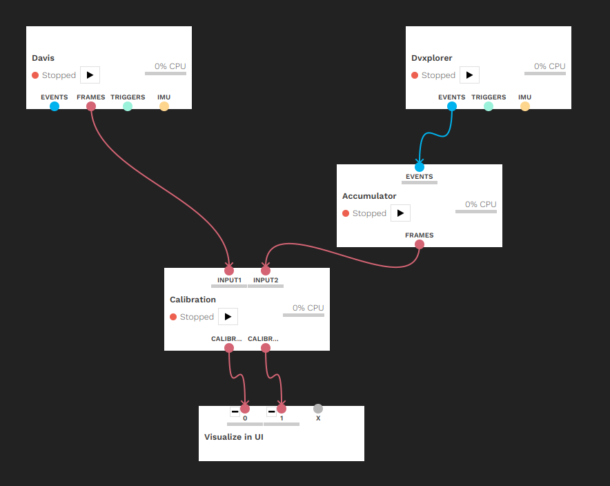
IMPORTANT: For stereo calibration, the two inputs need to be synchronized in time, for which a synchronization cable is required, and timestamps need to be reset from the master camera.
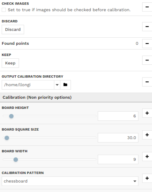
The following parameters must be set according to the calibration pattern: board height and width, square size and pattern type. The available patterns are the standard chessboard ( Download PDF), circles grid ( Download PDF) and asymmetrical circles grid ( Download PDF). In this tutorial, the 6 x 9 chessboard with a square size of 30 mm is used. So the width should be set to 9, the height to 6 and the square size to 30mm; these are already the default values. It should be noted that the square size can be expressed in any length scale.
A few notes about calibration patterns:
if you use our default patterns above, you can press the Use Default Pattern button in the configuration after selecting the appropriate pattern type, and it will automatically fill out all the sizes with the correct values.
if you want to generate your own patterns, calib.io has a very usable pattern generator, as well as printed patterns for sale.
do not use square pattern sizes (i.e. 4x4, 8x8), nor symmetric ones (i.e. 6x8, 12x22), and use asymmetric patterns instead (one dimension even, one odd, i.e. 5x8, 10x19). This greatly helps calibration to figure out the proper orientation of the pattern and leads to better detections and results. A pattern size of at least 4x5 is recommended.
chessboard pattern: pattern width and height are the respective number of squares, and the square size is the size of one square’s side.
circles grid pattern: board width and height are the respective number of circles, and the square size is the distance between the centre of two consecutive circles.
asymmetric circles grid pattern: width is the number of circles per row/column that stays constant, and height is the number of such groups. The square size is the distance between the centre of two consecutive circles on the same row/column.
Additionally, an output directory can be defined under which the calibration results are saved. By default, or if the field is left empty, the home directory is used.
The calibration procedure is now ready to begin.
Calibrating
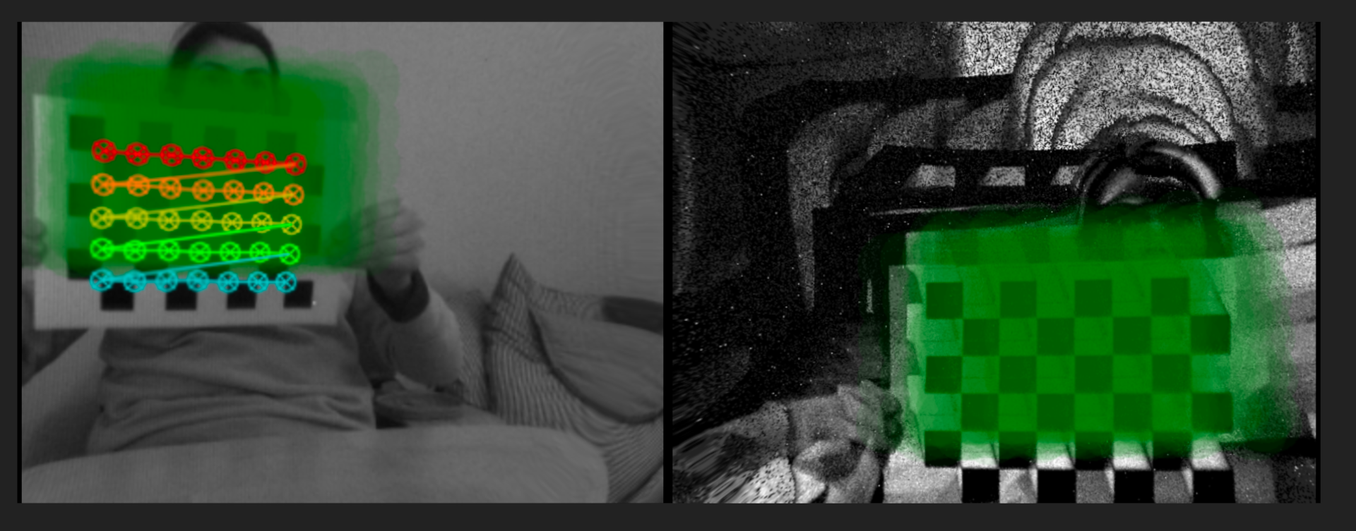
Click “run” on the calibration module. Start moving the calibration pattern in front of the camera(s). In case the pattern is detected, it will be drawn on the output image. The module collects a certain number of images for the actual calibration. This number can be set in the configuration panel under Min Detections. An image is added to the collection once the pattern has been consistently detected over a certain number of frames, configurable under Consec Detects. A log message will appear once an image has been added.
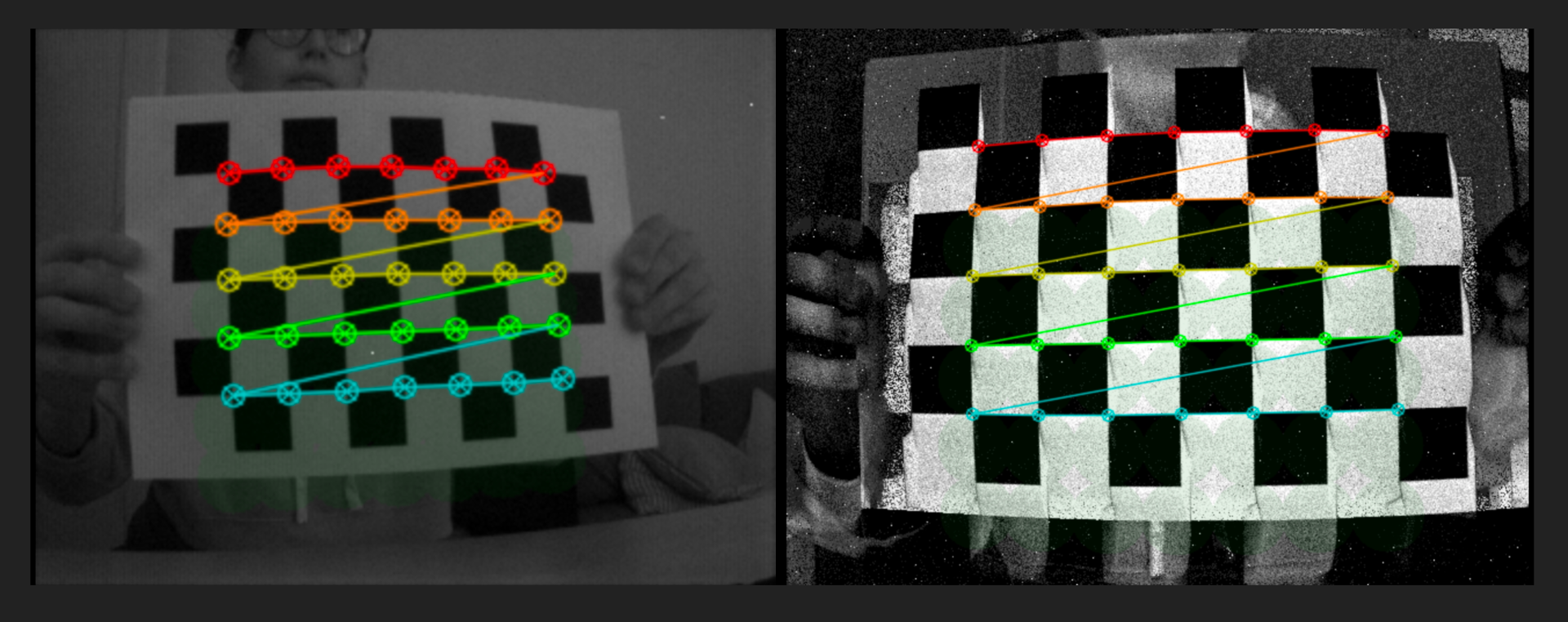
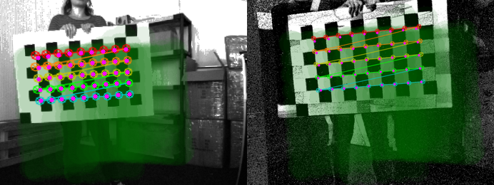
The area where a pattern has been found and added will turn slightly green. To get a good calibration result, one should cover the whole image in an even green shade. This can be turned off by unchecking the Highlight Area option.
Once enough images have been collected, they can be verified by the user if Check Images is ticked. One after another, the saved images and the detected patterns are shown. The user can choose to Keep or Discard them by pressing the corresponding buttons in the configuration panel. To get good calibration results, it is important to discard images where, although the pattern has been detected, some points are inaccurately placed or misaligned with the others or if too many images have been collected in a sub-region of the image.
New images are collected to replace the discarded ones, and once all pass the check, the calibration calculation begins. There may be some lag during the calculations, depending on the hardware and number of images used.
There are two error metrics. The maximum allowable error can be set under Max Reprojection Error. For stereo calibration, additionally, the error resulting from the epipolar line constraint is calculated and can be set under Max Epipolar Line Error. For the stereo calibration, both tests need to pass.
The epipolar line error is calculated as the mean epipolar error for every point in all the collected image pairs. For each pair of images, the error is computed as the sum of the distances d() between the points in one camera and the epipolar lines calculated from the other camera (m is the number of acquired images and n the number of points).

If the calibration is accurate enough, it is saved in the output directory, and the undistorted output from the camera(s) is shown. It is also possible to select the Save Images option to save the images used during the calibration in .png format.
If the calibration has been unsuccessful, it should be restarted with an increased number of images. To restart from the beginning with no stored images, simply stop and start the module again.
Additional options for stereo calibration
Calibrating two cameras with different resolutions requires both cameras to be calibrated separately first. The module tries to do this with the images provided to the stereo setup, however, this might not lead to good results for both cameras. In this case, both cameras should be calibrated independently using the calibration module with just one input. The saved results can be loaded for both inputs under Input1 Calibration File and Input2 Calibration File or alternatively from Input Stereo Calibration File.
In case the cameras have been successfully calibrated, epipolar lines can be drawn for the detected pattern if Draw Epipolar Lines is checked. This serves as a way to verify visually if the stereo calibration has been successful.
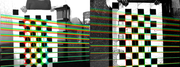
Another option for the stereo calibration is the possibility to draw the reprojected points from one camera to the other. You can select the Draw reprojected points option. This setting uses the Homography matrix (H) calculated during the calibration to map points from one camera to the other.
The option Save Stereo Statistics generates .csv files with the mean reprojected error of each acquired image from the two cameras.
Undistortion
Once calibration files have been generated for a camera, its event and frame outputs can be undistorted using the ‘undistort’ module. The module will try to verify that the data in the file applies to the connected camera inputs. Use one ‘undistort’ module instance per camera.
Improve calibration
ACCUMULATOR: For calibrating cameras that have only events available it is important to tune the accumulation parameters. Rising Event contribution increases the image contrast and facilitates pattern detection (e.g. around 0.05).
ACCURACY: For mono calibration, if the reprojection error is too high, it is possible to improve it by increasing the number of acquired images and ensuring that they cover the whole Field-Of-View of the camera. This is true also for stereo calibration and the epipolar error. In this latter case, calibration can also be improved by loading the single camera calibration matrices in Input1 Calibration File and Input2 Calibration File from previous mono calibrations.
SAVING: The current implementation saves the calibration files only if the calibration errors satisfy the requirements. Increase the Max Reprojection Error or Max Epipolar Error if you want to always save the calibration results.