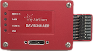
DAVIS346 AER
Date: 2026-05-26
Prototype DAVIS sensor in 180 nm CIS technology
Concurrent QVGA+ (346 x 260) resolution event and frame output from single sensor via USB
Event-only output via AER connector
Event output with up to 120 dB dynamic range, sub 1 µs latency, 1 µs temporal resolution and up to 12 million events per second throughput
6-axis IMU, up to 8 kHz sampling rate
Consumes less than 180 mA at 5 V power supply
Anodized aluminium case with CS lens mount, 4-side mounting options
Screw-locked USB port and fully isolated multi-camera sync ports
Specifications
Event Output
Description |
Value |
|---|---|
Spatial Resolution |
346 x 260 |
Temporal Resolution 1 |
1 µs |
Typical Latency 2 |
<1 ms |
Max Throughput |
12 MEPS |
Dynamic Range |
~ 120 dB (0.1-100k lux with 50% of pixels respond to 80% contrast) |
Contrast Sensitivity |
14.3% (on) 22.5% (off) (with 50% of pixels respond) |
1 The temporal resolution is characterized by the timestamp unit. In fact, a timestamp unit of 1 us offers minimum gain over a timestamp unit of 200 us. For more explanation, please refer to our white paper.
2 The temporal latency is given as a nominal number and can be improved with strong lighting or optimised biases.
Frame Output
Description |
Value |
|---|---|
Spatial Resolution |
346 x 260 |
Frame Rate |
40 FPS |
Dynamic Range |
55 dB |
FPN |
4.2% |
Dark Signal |
18000 e-/s |
Readout Noise |
55 e- |
Color Event and Frame Output
We provide both a mono (grayscale) and a color version of DAVIS 346. The mono version is a monochrome sensor and the color version is a color sensor that uses a Bayer color filter (RGGB as seen in the image below) for both events and frames. By default, the camera uses demosaicing for reconstructing RGB frames. In order to change to raw color output, please refer to DV software or dv-processing. Note that the color frames are not calibrated, and thus do not faithfully reproduce the real observed color.

IMU
6-axis (Gyro + Accelerometer), up to 8 kHz sampling rate. The IMU is synchronized with the event and frame output. Read more in the IMU section.
Camera Synchronization / Trigger Input
Multi-camera synchronization and external triggers are not supported. The AER output does not have a concept of time or timestamping, so there is also no concept of synchronizing multiple cameras directly. You can do this on your own FPGA as needed.
Other Attributes
Description |
Value |
|---|---|
Dimensions [mm] |
W 40 x H 60 x D 25 |
Weight |
120 g without lens |
Lens Mount |
CS-mount |
Case Material |
Anodized aluminium |
Mounting Options |
4-side Whitworth 1/4”-20 female and M3 mounting points |
Connectors |
USB 3.0 micro B port with locking screw, AER connector with 2.54 mm pins |
Multi-cam sync |
No |
Power Consumption |
<180 mA @ 5 VDC (USB) |
Sensor Technology |
0.18 µm 1P6M MIM CIS |
Pixel Pitch [µm] |
18.5 µm |
Sensor Supply Voltage |
1.8 V and 3.3 V |
Certifications |
None |
Specifications not guaranteed. All specifications subject to change without notice.
Sensor Limitations
In APS GlobalShutter mode, bursts of DVS events can be caused by the capture of an APS frame.
Due to bandwidth limitations, the DVS event output tends to follow a scanning pattern when under high load.
The frame output has below average performance in terms of image quality compared to conventional image sensors.
Color frames are not calibrated, and thus do not faithfully reproduce the real observed color.
The event output can be destabilized if a strong light source impacts a sensitive spot outside the photosensitive pixel array.
The AER connector can only transmit events, not frames or IMU data.
No multi-camera timestamp synchronization is present, nor external triggers.
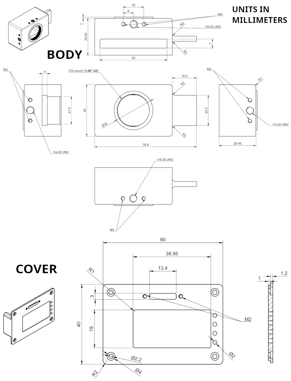
Physical Dimensions
The DAVIS camera is housed in an anodized aluminum case. The case dimensions are depicted below.
Connectors
DAVIS 346 AER has one USB 3.0 connector for data and power on its back, as well as an AER connector to the side. Please note no timestamp synchronization and/or trigger connectors are provided on this model!
USB 3.0 Connector
The USB 3.0 Micro B connector is used for data and power. Any USB 3.0 or USB 2.0 cable with Micro B type connector can be used. However, USB 3.0 speeds are only supported when using a USB 3.0 cable. Usage of cables with appropriate locking screws are recommended for a more secure and robust connection.
Warning
The USB cable must always be connected for the device to work, even when using the AER interface.
AER connector
The AER connector is located on the side, as shown in the following image:
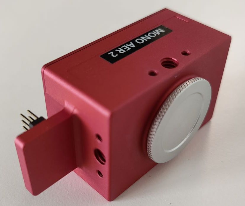
It consists of 16 (2x8) 2.54mm pins. The exact pinout is marked on the connector itself, as shown here:
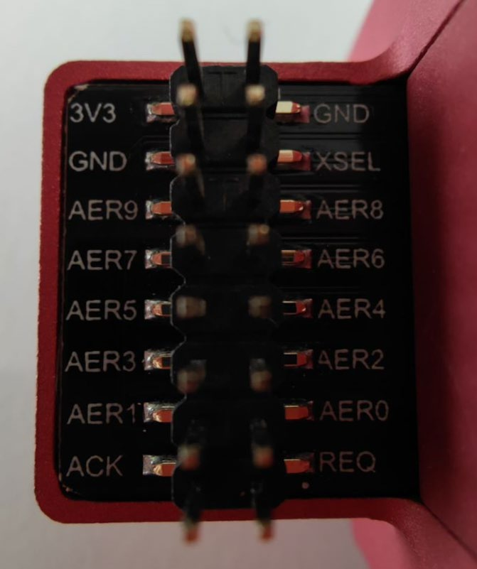
All data pins are 3.3V. A 3.3V reference and its Ground (GND) reference are provided on the connector. The 3.3V pin is only intended as a reference/output, do not power the device using this pin! The USB connector must be used always to provide power and configuration.
The protocol is documented below.
Optics
The camera lens mount is designed to accommodate CS-mount lenses. Other lenses can be accommodated by using adapters. The standard lens shipped with the camera is a C-mount lens and ships with an adapter. The chip requires a lens designed for 1/2” imagers.
The field of view (FOV) depends on the focal length L of the lens and the size W of the pixel array. It is computed from geometrical optics, not accounting for any lens distortion. The angular field of view (AFOV) is given by:
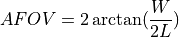
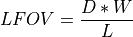
The linear FOV (LFOV) at a distance D from the lens is given by:
The pixel array has a resolution of 346 x 260 and measures:
Width: 346 pixels x 18.5 µm/pixel = 6.4 mm
Height: 260 pixels x 18.5 µm/pixel = 4.81 mm
Diagonal: 8 mm
Field of View Computations
The following table shows the horizontal and vertical field of view in degrees and its size at various distances for different common focal lengths.
Lens Focal |
Horizontal Angular |
Vertical Angular |
Diagonal Angular |
Horizontal Linear FoV |
Horizontal Linear FoV |
Horizontal Linear FoV |
Horizontal Linear FoV |
|---|---|---|---|---|---|---|---|
2.10 |
113.46 |
97.75 |
124.64 |
30.48 |
91.44 |
304.81 |
609.62 |
2.80 |
97.64 |
81.32 |
110.06 |
22.86 |
68.58 |
228.61 |
457.21 |
3.00 |
93.70 |
77.44 |
106.31 |
21.34 |
64.01 |
213.37 |
426.73 |
3.60 |
83.28 |
67.49 |
96.07 |
17.78 |
53.34 |
177.81 |
355.61 |
4.50 |
70.84 |
56.24 |
83.32 |
14.22 |
42.67 |
142.24 |
284.49 |
6.00 |
56.15 |
43.69 |
67.43 |
10.67 |
32.01 |
106.68 |
213.37 |
9.00 |
39.15 |
29.92 |
47.96 |
7.11 |
21.34 |
71.12 |
142.24 |
12.00 |
29.87 |
22.67 |
36.90 |
5.33 |
16.00 |
53.34 |
106.68 |
16.00 |
22.62 |
17.10 |
28.10 |
4.00 |
12.00 |
40.01 |
80.01 |
Additional Information
Software
DAVIS 346 AER is compatible with all our software. You can use it in:
To enable the AER output connector, in DV open the Capture module full configuration (+ sign) and turn on the
ExternalAERControl parameter.
For a low-level approach, there is also an example using libcaer to enable this feature on our developer website:
AER protocol format
The AER protocol is a simple protocol using a variable number of lines (bus) to transmit data, and two lines (REQ and ACK) to synchronize the data between the sender and the receiver asynchronously using a four-phase handshake (this is also called a bundled asynchronous protocol). The ACK and REQ lines are active-low. This is how the protocol looks from the receiver’s perspective, where REQ is to be considered an input and ACK an output:
The receiver waits for the REQ line to be asserted by the sender
At this point, the data on the bus can be considered valid and stored
The receiver confirms having read the data by asserting ACK
It then waits until the sender has again deasserted REQ, deasserts ACK itself and goes back to wait in (1) for the next transaction
The following website has number of very detailed explanations for further reading:
https://www.cl.cam.ac.uk/~djg11/wwwhpr/fourphase/fourphase.html
Also, for details on AER, please look at:
https://www.ini.uzh.ch/~amw/scx/std002.pdf
For FPGA implementations, we recommend synchronizing at least the REQ input using a double-flip-flop synchronizer. Data itself should also synchronized in this way, or by connecting it directly to a register with an Enable signal and enabling it only during phase (2). All current iniVation DAVIS sensors employ a serial data format, meaning that the X and Y addresses are not output concurrently, but separately one after the other. One extra data bit, called XSelect, is used to disambiguate between the two types of address. Current sensors employ a row-wise readout scheme, so a Y (row) address will always be followed by a series of one or more X (column) addresses. The column address will also contain the Polarity information bit. Further, we recommend inserting a delay of ~50ns between REQ and getting the data (phases 1 and 2), because the current sensors violate the assumption that all data lines are always valid and stable before REQ is asserted. The XSelect bit can be considered valid right away, but for Y addresses this delay should be observed. X addresses can also be captured right away.
Note
DAVIS sensors may produce glitches known as “row-only events”, where a Y (row) address is followed immediately by another Y (row) address. In this case, just discard the earlier address.
The format for DAVIS346 AER is documented in detail below:
AER bus width: 11 signals = 10 (9 downto 0) + XSelect

if XSelect = '1' then
  X Address, address is: 9 bits, 9 downto 1, polarity on 0
else
  Y Address, address is: 9 bits, 8 downto 0, 9 is don't care
end if;
FPGA receiver state-machine
An example VHDL state-machine for FPGAs is provided to interface with the AER connector and receive event data off the device:
Serial Number
The serial number of the device can be found on the case, usually a four-digit number printed on a black label located at the top of the camera case.
Package Contents
DAVIS 346 AER ships with the following items:
DAVIS 346 AER camera
USB 3.0, 1m with locking screws
Varifocal C mount lens ( Datasheet)
CS to C mount lens adapter
Tripod
Safety Information
To prevent damage to property or injury to yourself or to others, read this safety information in its entirety before using this product.
This product is intended to be used in a laboratory and for industrial applications under controlled conditions.
We strongly recommend that you only use high quality USB cables, like the ones provided by iniVation. Using low quality USB cables could cause damages to the device.
Keep the product dry. Do not handle the product with wet hands. Do not handle the plug with wet hands. Do not operate the camera near water. This could cause damage to the device. The camera is not water-safe.
Handling: Handle your product with care. It is made of metal, glass, and plastic and has sensitive electronic components inside. The product can be damaged if dropped, burned, punctured, or crushed, or if it comes in contact with liquid. If you suspect damage to the product, please contact iniVation.
Repairing: Do not open the product and do not attempt to repair the product yourself. Disassembling the product may damage it and will void your warranty. If your product is damaged or malfunctions, please contact iniVation.
Do not disassemble or modify this product.
Do not touch internal parts that become exposed as the result of a fall or other accident.
Keep this product out of reach of children. Should a child swallow any part of this product, seek immediate medical attention.
Use travel converters or adapters designed to convert from one voltage to another or with DC-to-AC inverters.
Explosive and other atmospheric conditions. Connecting or using the product in any area with a potentially explosive atmosphere, such as areas where the air contains high levels of flammable chemicals, vapors, or particles (such as grain, dust, or metal powders), may be hazardous. Exposing the product to environments which have high concentrations of industrial chemicals, including near evaporating liquified gasses such as helium, may damage or impair the product’s functionality.
Turn this product off when its use is prohibited.
Do not leave the product where it will be exposed to elevated temperatures for an extended period such as in an enclosed automobile or in direct sunlight. This can lead to malfunction.
Correct Disposal

This product and its electronic accessories should not be disposed of with
other household waste. If you are unable to dispose of this item safely please return it to iniVation AG.
CE Certification
DAVIS 346 AER is currently not certified for any purpose.