IMU
The IMU used in our DAVIS346 camera is the TDK InvenSense MPU-6500 ( Datasheet). All other cameras use Bosch BMI-160 imu ( Datasheet). Before continuing notice that we refer to image sensor as the sensor outputting events, or events and frames in case of DAVIS346.
For several applications related to tracking, IMU can be useful. This sensor provides both angular speed and linear acceleration information. Our cameras output angular speed as (degrees/second) and linear acceleration using gravity acceleration constant as unit (g). Note that to convert acceleration to m/s^2 you need to multiply the accelerometer values by the gravity constant (1g = 9.81m/s^2). In order to be able to combine these data with image-based motion estimation, the relative position and orientation between the image sensor and the IMU is needed.
The following drawing shows the camera axis and the rotation directions for positive angular velocity.
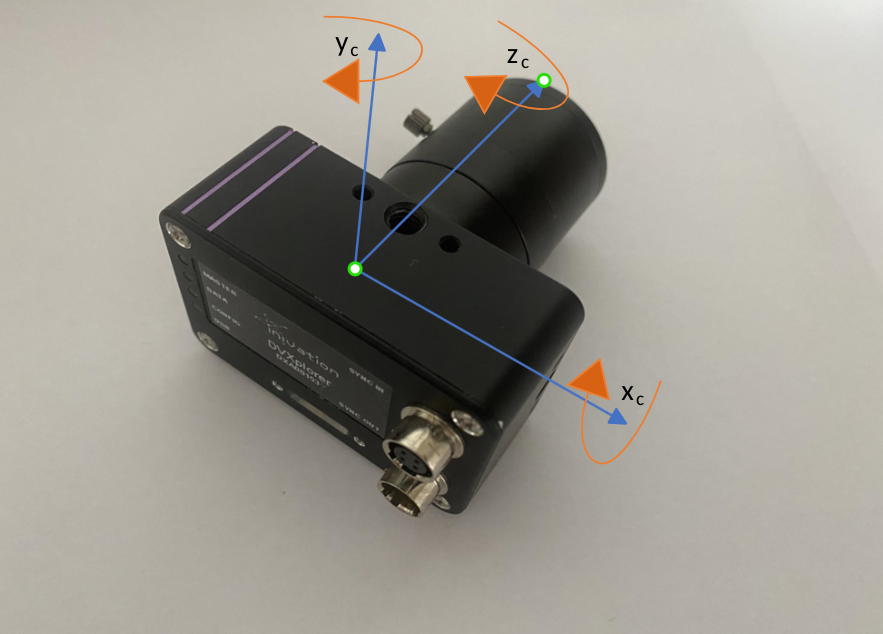
The image sensor uses the standard format: by looking at the camera from the back, X-axis points to the right, Y-axis up and Z-axis points towards the lens. In addition, the IMU axis are aligned with the camera one. The rotation for the gyroscope is counter-clockwise along the increasing axis, for all three axes. Note that, this does not follow the right-hand rule.