External Input Triggering and Clock Synchronization
Several iniVation cameras have extra input and output ports to support special multi-camera setups, let’s start by defining the supported features and what they do in this context:
External Input Triggering
This feature allows a limited form of interaction with third-party cameras and systems, using the INPUT_SIGNAL and OUTPUT_SIGNAL ports.
The INPUT_SIGNAL port can be configured to detect rising edges, falling edges and pulses originating from another camera or electronic system, and when it detects such an occurence, a special data point is inserted into the data stream coming from the iniVation camera, with a very precise timestamp, allowing data from the camera to be put in relation with events happening externally.
This feature can detect signals up to a theoretical maximum of 1 MHz. For square wave inputs, we recommend just detecting the rising edges and not going above 100 KHz frequency for reliable results. No debouncing or signal cleanup is attempted.
Best case would be to just send a pulse when the external camera captures a frame, so you can correlate the two. A lot of machine vision cameras support that kind of trigger, for example to flash external LED lights.
This does not change how the iniVation camera itself operates, so it isn’t possible to start/stop recordings, configure the camera or trigger frame captures on DAVIS using this feature.
The OUTPUT_SIGNAL port simply relays the INPUT_SIGNAL port by default, allowing daisy-chaining of this detection feature. Some iniVation cameras also support generating a PWM-like signal on this port as a configurable option. The signal output is not directly related to camera operation; it does not signal changes to the camera state such as starting/stopping a recording or data acquisition. The table below lists all cameras supporting this extra feature.
All of this has to be configured and enabled using our software, the options are usually called ‘External Input Detector’ for the detection part on the INPUT_SIGNAL port and ‘External Input Generator’ for the optional PWM signal generation on the OUTPUT_SIGNAL port.
Clock Synchronization
The clock synchronization feature allows multiple connected cameras to keep their microsecond-precision timestamps synchronized with each other using the INPUT_CLOCK and OUTPUT_CLOCK ports.
One of the main features of iniVation cameras and their event output is its precise timing, so when multiple cameras are used in parallel to record the same scene (stereo configurations), it is important that this timestamp keeps the same value on all cameras. This mechanism is only recommended to keep time synchronized between iniVation cameras and is not intended for third party usage.
Cameras are connected in a daisy-chain, and as soon as a physical connection is established with a cable, they automatically synchronize (details on synchronization protocol here). The first camera in the series, the one without a signal on INPUT_CLOCK, is called the Master camera, and will have its Master LED turned on. The other cameras will have the LED turned off. Synchronization status can also be checked in our software, where the option ‘deviceIsMaster’ normally informs the user about a camera’s status.
Once all cameras are hardware synchronized, you simply have to reset the timestamp of the Master camera, which will then reset all the downstream devices too, ensuring that all of them have the same start point in time. This is done via software, either manually by selecting the ‘Reset Timestamps’ option or by using dv-processing’s Stereo classes which do this automatically.
Hardware
The following table contains a quick overview of which iniVation camera models support external input triggering and clock synchronization:
Model |
Supports clock synchronization and external input triggering |
Supports PWM signal generation (OUTPUT_SIGNAL) |
Used connector |
Supported voltage |
|---|---|---|---|---|
YES (old protocol) |
NO |
2.54mm pins |
3.3V |
|
YES |
YES |
HiRose HR10A-7R-4P / HR10A-7R-4S |
3.3V-5V |
|
YES |
NO |
3.5mm audio jack |
5V |
|
YES |
YES |
HiRose HR10A-7R-4P / HR10A-7R-4S |
3.3V-5V |
|
YES |
YES |
HiRose HR10A-7R-4P / HR10A-7R-4S |
3.3V-5V |
|
YES |
YES |
HiRose HR10A-7R-4P / HR10A-7R-4S |
3.3V-5V |
|
DVXplorer Mini |
NO |
NO |
- |
- |
eDVS |
NO |
NO |
- |
- |
DVS240, DAVIS346, DVXplorer, DVXplorer Lite
The newest camera models have two connectors on the backplate; the OUTPUT SYNC connector is a HiRose HR10A-7R-4P (male) and the INPUT SYNC connector is a HiRose HR10A-7R-4S (female).
Cables should use the matching connectors HR10A-7P-4S (female) and HR10A-7P-4P (male).
The following supplier can build such cables to order: Raymo.
The pinout is shown in the following image:
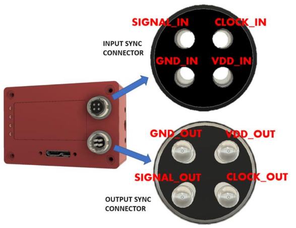
Input signals can be 3.3V or 5V, depending on the VDD_IN supplied externally. GND_IN and VDD_IN must always be supplied.
Output signals are always 5V, as is VDD_OUT in relation to GND_OUT. If you chain cameras together for synchronization, the clock and VDD will be 5V, for example.
Please note that all the pins in the INPUT SYNC connector are isolated from the OUTPUT SYNC connector. To keep full electrical isolation between different cameras, the cable should not be shielded, or if it is, the shield should not connect one end of the cable to the other.
If the CLOCK_IN signal is not being used, we strongly recommend shorting it to VDD_IN, to provide a stable known value. Failure to do so often leads to coupling on the CLOCK_IN line, for example from a signal on the SIGNAL_IN line, which then leads to spurious timestamp resets on the camera, which can strongly affects its performance.
For the purpose of clock synchronization, as soon as the cameras are connected they will automatically synchronize time and figure out their arrangement; the first camera’s Master LED (see description on backplate) will remain lit, while the other camera’s will turn off.
DAVIS240
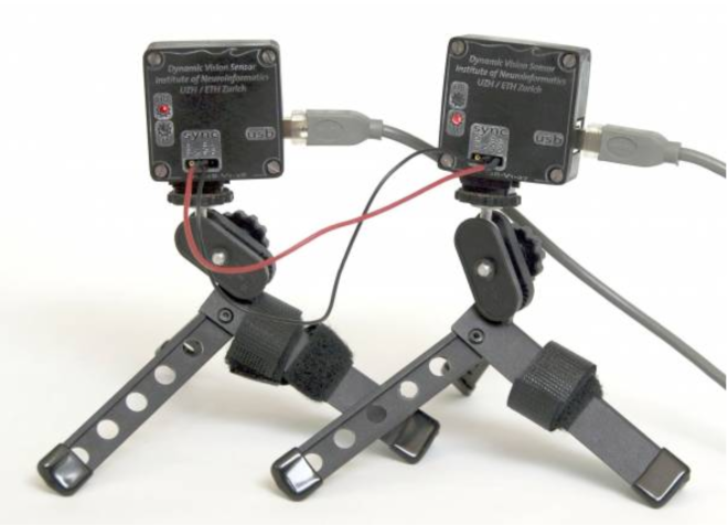
Two 3.5mm audio jacks, labeled IN and OUT (printed backwards on the PCBs), are used by these cameras to enable synchronization features.
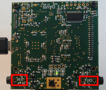
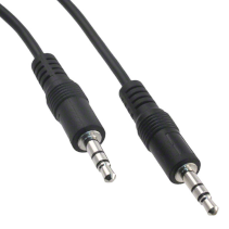
Any 3.5mm audio cable can be used to connect camers to each-other, and can be found at any AV store or suppliers such as digikey.
To access the clock synchronization and external input triggering features separately, or to more easily integrate with third party systems, audio connectors that split the jack into two RCAs can be used:
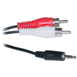
Each audio jack has the following pinout:
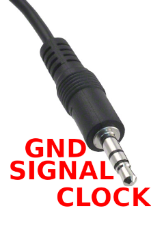
External first circle from the cable, “sleeve”: GND (Ground)
External second circle: SIGNAL
Tip: CLOCK
The voltage for SIGNAL and CLOCK, both on the IN and OUT sides, is 5V.
For the purpose of clock synchronization, as soon as the cameras are connected they will automatically synchronize time and figure out their arrangement; the first camera’s Master LED (LED1) will remain lit, while the other camera’s will turn off.
DVS128
This camera only exposes a few simple 2.54mm pins: IN, OUT and GND.
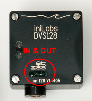
You can connect these using simple copper cables or jumper wire.
The signal on the IN pin has to be 3.3V. DO NOT connect this with devices providing a 5V signal, such as the DAVIS240!
The OUT pin will always produce a 3.3V signal.
In the old synchronization protocol, a device must be told via software whether it is a master, which produces the synchronization signal, or whether it is a slave, which receives it. Further, the DVS128 has only one pin each for input and output, leading to a more limited set of modes of operation:
camera configured as Master (sender) via software: the IN pin can be used for external input triggering by detecting rising edges only, the OUT pin will generate the clock synchronization signal.
camera configured as Slave (receiver) via software: the IN pin can only receive the clock synchronization signal from another camera, the OUT pin will repeat the clock synchronization signal.
To configure the camera in these two modes, please first make sure that it is running the latest firmware version 14. By default a DVS128 will be in Master mode. The Master camera keeps its bottom LED on, while the others have it turn off.
When using dv-processing, you will find a setMaster() function in the dv::io::camera::DVS128
class, respectively in DV you’ll find a ‘Set Master’ checkbox in the module configuration.
In libcaer (deprecated), you can use the following C++ code to switch modes:
deviceHandle.configSet(DVS128_CONFIG_DVS, DVS128_CONFIG_DVS_TS_MASTER, true/false);
Software
DV
To view the clock synchronization status for a supported device in DV, open the extended camera module configuration (plus sign in right-hand menu) and search for the ‘Device is Master’ checkbox, as well as the ‘Sync Status’ field.
To properly synchronize multiple cameras, please execute the following procedure:
Make sure all cameras are connected and hardware synchronized, check their LEDs. Only the first Master LED should be turned on.
Add all required camera modules to DV.
Start all camera modules.
On the Master clock camera module, open its configuration and edit the ‘Sync With’ field by adding the module names of all secondary cameras, comma separated (for example: “dvx1,dvx2,davis1”).
On the Master clock camera module, open its configuration and click on the ‘Sync Time’ button. You will have to repeat at least this step manually every time you restart DV, even if loading from a saved project.
Done! A series of messages should be printed in the log console, one for each camera, all with the same real-time offset. All cameras are now hardware synchronized and use the same real-time offset, all timestamps are directly comparable.
The “triggers” output of the camera module in the DV software will contain the external triggers data, each recorded trigger event will contain a timestamp and a type set to either EXTERNAL_SIGNAL_RISING_EDGE or EXTERNAL_SIGNAL_FALLING_EDGE depending on detector configuration, as it can react to raising edges and/or falling edges.
To enable the external signal detector in our software, open the detailed configuration of the camera module (plus sign in right-hand menu) and search for ‘detector’, you’ll then be shown the options for it. Turn on rising or falling edge detection, and then press the ‘Detector Run’ button. You can then connect the “triggers” output to the file output module (“Record” project) to write the data out to a file, together with the events, and then process them offline.
dv-processing
Open each camera normally, using their device classes (dv::io::camera::DAVIS, dv::io::camera::DVXplorer, …) or using the function ‘dv::io::camera::openSync(serialNumber)’. Member functions ‘isMaster()’ and ‘isSynchronized()’ of the device classes allow checking of current camera clock synchronization status.
To synchronize the cameras, pass a reference (or pointer) of each camera to the function ‘dv::io::camera::synchronizeAnyTwo(first, second)’. In case of three or more cameras, use the function ‘dv::io::camera::synchronizeAny(…)’.
C++ example code is available in samples/io/stereo-capture/stereo-capture.cpp. A Python version is available in python/samples/stereo_camera_capture.py.
libcaer (deprecated)
To check the clock synchronization status for a device using libcaer, use the following C++ code:
bool deviceIsMaster = deviceHandle.infoGet().deviceIsMaster;
Once you have confirmed correct synchronization between all cameras (only one Master camera should be present), you must reset the timestamp on the Master camera only so that they all start from a common time point. You can use the following C++ code to reset timestamps:
DVS128:
masterDeviceHandle.configSet(DVS128_CONFIG_DVS, DVS128_CONFIG_DVS_TIMESTAMP_RESET, true);

DAVIS:
masterDeviceHandle.configSet(DAVIS_CONFIG_MUX, DAVIS_CONFIG_MUX_TIMESTAMP_RESET, true);

DVXplorer:
masterDeviceHandle.configSet(DVX_MUX, DVX_MUX_TIMESTAMP_RESET, true);
Resetting the timestamp will generate a data packet of type caer_special_event_packet with one event of type
caer_special_event, containing a timestamp and the type set to TIMESTAMP_RESET.
Running the external signal detector will result in data packets of type caer_special_event_packet with events of type
caer_special_event, containing a timestamp and the type of the detected signal: EXTERNAL_INPUT_RISING_EDGE or
EXTERNAL_INPUT_FALLING_EDGE.
The C++ code below will enable the detector and configure it to report rising edges in the signal:
DAVIS:
deviceHandle.configSet(DAVIS_CONFIG_EXTINPUT, DAVIS_CONFIG_EXTINPUT_DETECT_RISING_EDGES, true);
deviceHandle.configSet(DAVIS_CONFIG_EXTINPUT, DAVIS_CONFIG_EXTINPUT_RUN_DETECTOR, true);

DVXplorer:
deviceHandle.configSet(DVX_EXTINPUT, DVX_EXTINPUT_DETECT_RISING_EDGES, true);
deviceHandle.configSet(DVX_EXTINPUT, DVX_EXTINPUT_RUN_DETECTOR, true);
Appendix
Clock Synchronization Protocol Details
In protocol 1 (DVS128 only), a device must be told whether it is a master, which produces synchronization pulses, or whether it is a slave, which receives synchronization pulses.
In protocol 2 (all other cameras), a device assumes that it is a master, unless it is receiving synchronization pulses, in which case it assumes it is a slave automatically. This simplifies setup.
In both protocols a 10 KHz clock is used to advance the timestamps. In slaves, timestamps are allowed to advance on the falling edge of the clock. If the falling edge is delayed by a small period - up to 16 µs for protocol 1, and up to 10 µs for protocol 2 - then any events in that waiting period continue to take the same timestamp until the falling edge is detected.
After the small period, it is assumed that a falling pulse represents a reset pulse. The reset pulse is supposed to last 200 µs.
In protocol 1, slave devices pause their clock indefinitely until the next falling edge, at which point they reset their clock and then continue to increment it. In protocol 2, if the falling edge is not received within 210 µs from the previous falling edge, then the device assumes that it has become a master itself, having lost connection with its previous master; at this point it resets its clock, starts to increment it and sends out a 10 KHz synchronization clock of its own.
It’s also possible to fake a master by generating a clean 10 KHz clock (50% duty cycle) and a 200 µs reset pulse and feeding these into the first device in the chain, by using external hardware such as a programmable function generator.