AEDAT 2.0
Version 2.0 was introduced in 2010. It is equivalent to version 1.0, but widens the address field to 32 bit. It also requires the header version line to disambiguate between formats. Then again, an optional header, followed by a series of [address, timestamp] pairs, each making up an event. The address is 32 bit wide, and the timestamp is also 32 bit, a total of 8 bytes per event. The timestamp is in microseconds, while the address has to be interpreted according to a specific jAER AEChip class’ definition of that address. This could be the DVS128 class, the same as AEDAT 1.0, or the DAVIS family of classes (DAVIS240A,B,C; DAVIS346cBSI, DAVIS640, …). All integer data and fields are always signed and big-endian!
The jAER software, since 2014, also writes several informative header lines, these include the ‘HardwareInterface’ and the ‘AEChip’ header line contains information on the current device and the class interpreting its output. Here is an example of these informational lines:
# This is a raw AE data file - do not edit

# Data format is int32 address, int32 timestamp (8 bytes total),
peated for each event

# Timestamps tick is 1 us

# created Thu Dec 03 14:47:00 CET 2015

# HardwareInterface: DAVIS FX3 0002-INI

# AEChip: eu.seebetter.ini.chips.davis.Davis640
Further, a full XML-like dump of all the preferences for the above AEChip class, which includes settings such as the APS exposure time or the biases, is generated, and kept either fully in the header as header lines or, in the future, in a separate XML file, which is named
<filename>-prefs.xml
and is referenced in the header as one header line as follows:
# Prefs-File: <filename>-prefs.xml\r\n
Entries look like the following in XML (the example is of an addressable bias):
<entry key="DAVIS240C.AddressedIPotCF.ApsROSFBn.LowCurrent" value="false"/>
Ordering
All events in the AEDAT 2.0 format are ordered by their timestamp, and should guarantee timestamp monotonicity, meaning the next event will always have an equal or greater timestamp.
It is possible to find older files where this was not guaranteed due to older hardware and its logic sometimes not ensuring that timestamp increase events be always delivered. When this is the case, the software will detect this, warn the user and continue working by “jumping back” to the new but older timestamp value.
DAVIS
The DAVIS camera family stores polarity (luminosity change) events, IMU (Inertial Measurement Unit) samples and pixel intensity values (both APS reset and signal read) according to the following scheme:
Bit 31
Bits |
Meaning |
Description |
|---|---|---|
31 |
Type |
Defines the type of address stored here. ‘0’ means DVS, ‘1’ means APS or IMU (see bits 11-10). |
Bit 30-12
IMU:
Bits |
Meaning |
Description |
|---|---|---|
30-28 |
IMU sample type |
Type of IMU sample: |
27-12 |
IMU sample |
For IMU events, 7 words are sent in series, these being: |
DVS or APS:
Bits |
Meaning |
Description |
|---|---|---|
30-22 |
Y address |
Y event address. (0, 0) in the lower left corner of the screen. |
21-12 |
X address |
X event address. (0, 0) in the lower left corner of the screen. |
Bit 11-10
APS:
Bits |
Meaning |
Description |
|---|---|---|
11-10 |
sub-Type |
00 -> APS Reset Read |
DVS:
Bits |
Meaning |
Description |
|---|---|---|
11-10 |
sub-Type |
00 -> DVS Polarity OFF |
Bit 9-0
Bits |
Meaning |
Description |
|---|---|---|
9-0 |
ADC sample |
10-bit ADC sample representing pixel intensity. Only for Type=APS, else zero. |
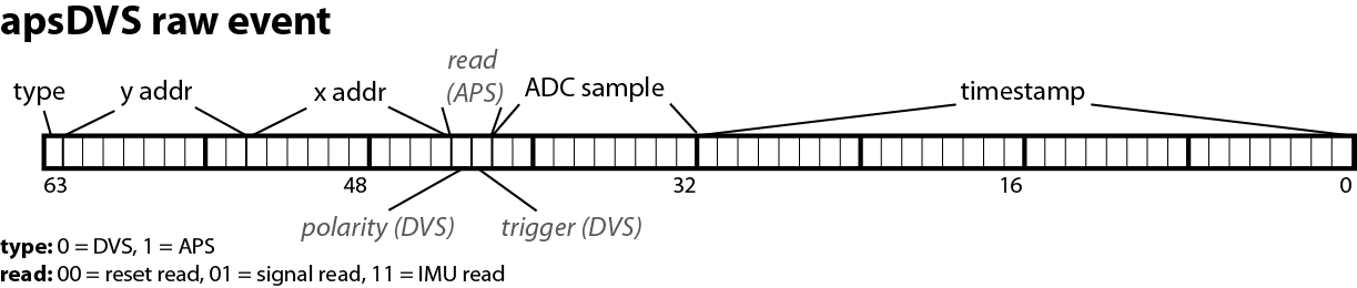
The following image explains the same thing in a more graphic way (IMU data is not shown in this graphic, however):
 Frames, in this format, are laid out as a sequence of
events, one for each pixel. The timestamp for each pixel is also stored and corresponds to the start of the readout of
the column where the pixel resides. To get start and end of frame and exposure timestamps, one has to look at the
timestamp of the pixel readouts closest to those moments:
Frames, in this format, are laid out as a sequence of
events, one for each pixel. The timestamp for each pixel is also stored and corresponds to the start of the readout of
the column where the pixel resides. To get start and end of frame and exposure timestamps, one has to look at the
timestamp of the pixel readouts closest to those moments:
Start of Frame: first reset read pixel.
Start of Exposure: last reset read pixel for GlobalShutter mode, first reset read pixel for RollingShutter mode.
End of Exposure: first signal read pixel.
End of Frame: last signal read pixel.
DAS1
The DAS1 (Dynamic Audio Sensor, CochleaAMS1c AEChip class) stores its data according to the following format:
Bit 13-10
Bits |
Meaning |
Description |
|---|---|---|
13 |
Type (ADC or AER) |
Defines the type of address stored here. ‘0’ means AER from Cochlea chip, ‘1’ means sample from external ADC. |
12 |
ADC scanner sync |
Signals if the current ADC sample is newly synchronized with the Scanner. If ‘1’, it is, so we can clear and reset buffers. If ‘0’, just get the ADC data. |
11-10 |
ADC channel |
Defines which of the four possible ADC channels this sample belongs to. |
9-0 |
ADC sample or AER address |
If Type=ADC, then this contains the 10-bit ADC sample ; If Type=AER, then this is the 10-bit AER address from the Cochlea chip. The 10 bits are to be interpreted this way: |
Bits from 9 to 0 are divided in the following way:
Bits |
Description |
|---|---|
9-8 |
Neuron number (0 to 3). |
7-2 |
Channel number (from 0 to 63, where 0 is the highest frequency, 63 is the lowest frequency). |
1 |
Left/Right ear (‘0’ is left, ‘1’ is right). |
0 |
Neuron bank (‘0’ if from BPF, ‘1’ if from SOS). |
Note that although the DAS1 has synchronization ports, the insertion of external trigger events into the event stream via a synchronization pulse has never been implemented in the firmware.